2.FEATURES:
- Monitoringanddisplay of the working status of electrostatic eliminators and sensors.
2. The working status of 4 ways equipment can be monitored simultaneously.
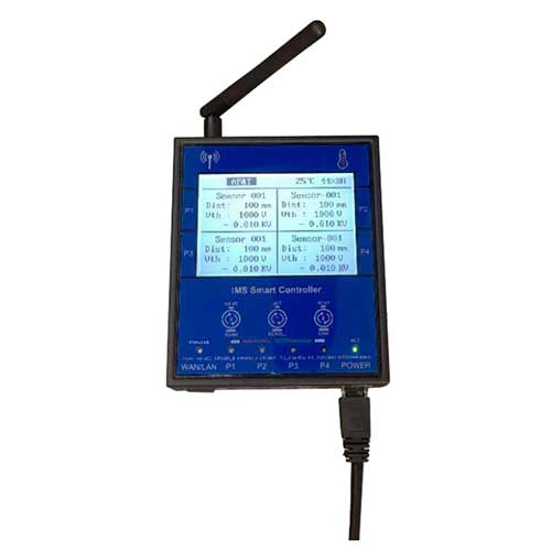
3. 4 ways working status indicator lights, 1 way communication status indicator light, and 1 way power-on indicator light.
4. RJ45 power supply and communication port.RS485 and wireless communication function.
3.SPECIFICATION:
| Specifications | |||||||||||||
| NO. | Parameter | ||||||||||||
| 1 | Adapter | IN:AC85-240V OUT:24V 2A | |||||||||||
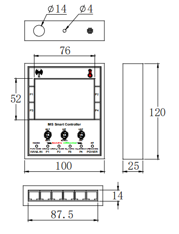
| 2 | Dimensions | 100*120*25 | |||||||||||
| 3 | Indication | LED | |||||||||||
| 4 | Digital display | 3.5 inch COG,monochrome | |||||||||||
| 5 | Working environment | Temperature:0-50℃;Humidity:30-70%RH | |||||||||||
| 6 | Product network port | 4 ways:P1-P4 | |||||||||||
|
7 |
Network port definition |
1、2 | 3 | 4 | 5、6、9 | 7 | 8 | ||||||
| White-orange/orange | White-blue | Blue | White-green/green | White-brown | brown | ||||||||
| VCC | RS485_B | RS485_A | GND、PE | NPN-C1 | NPN-C2 | ||||||||
| 8 | Communication network port | WAN/LAN | |||||||||||
| 9 | Power network port | POWER | |||||||||||
| 10 | Net weight | 400g | |||||||||||
| 11 | Gross weight | 500g | |||||||||||
| Function | |||||||||||||
| NO. | Parameter | ||||||||||||
|
1 |
Network port |
POWER | Power port(with RS485 communication method) | ||||||||||
| P1-P4 Note 1 | Eliminator or sensor | ||||||||||||
| WAN/LAN Note 2 | Ethernet connection | ||||||||||||
|
2 |
LED |
P1-P4 |
Red light |
Eliminator | High voltage indication |
Flashing |
|||||||
| Sensor | Threshold indication | ||||||||||||
|
Green light |
Eliminator |
Power-on indication |
Always on |
||||||||||
| Sensor | |||||||||||||
| Eliminator | Cleaning indication | Flashing | |||||||||||
| Note | |||||||||||||
| 1、P1 – P4 : Only 2 eliminators can be connected due to power limit of power supply | |||||||||||||
| 2、WAN/LAN : The power supply cannot be connected to this network port, otherwise the wireless module will be damaged | |||||||||||||
4.FUNCTION INTRODUCTION:
5.PRODUCT SIZE: