0865 735 110

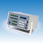
Two-input transmission deviation meter CRM-281  

Simultaneous value, integration difference, velocity, and speed difference can be analyzed in 100 μs on the same time axis.
Model: CRM-281
This is a transmission deviation meter that inputs 2 channels of pulse signals such as A/B phase signals and UP/DOWN signals of a pulse output type incremental encoder and calculates the integrated value of each and the integrated difference between the two channels.
The speed of ch A and ch B and the speed difference are also calculated at the same time.
In addition to displaying the angle and rotation speed, the number of pulses and frequency can also be displayed.
Since the analog output of the calculation is updated by 100 μs and 8 channels simultaneously, it is possible to analyze the integrated value, the difference in integration, the difference in speed, and the difference in speed on the same time axis.
Main Specifications option catalogue External dimensions Application examples Contact us
Instruction manual DXF Download ソフトウェア
Product features
■ 2ch simultaneous sampling
Since the counters of CH A and CH B are read at the same time, the sampling time difference between the 2 channels is small, and the maximum is within 5 μs.

■High-speed arithmetic By adopting a
32-bit RISC CPU, analog output update of 100 μs has been realized.

■ A/B phase signal max 1MHz input
Two-phase signals can be measured up to 1 MHz, internally multiplied by 4 to measure losslessly, and UP/DOWN and single-phase inputs can be input up to 2 MHz.
An optocoupler differential line receiver circuit is used for the pulse input, and the balanced input is resistant to common-mode noise and isolated.

■ Multi-form input signal support
Line drivers, general voltage signals, and non-voltage switch signals (open collectors, etc.) inputs are also supported as standard.
The A/B phase signal and the UP/DOWN signal can be switched by the program setting, and the signal form can be changed by connector or terminal termination.
It can be used with a variety of input devices.

■ Speed ratio setting Multiply the
chA input by the speed ratio (see the equation below) and calculate the integration difference even if the input frequency is different.
chA×R1/R2 can be set to display the value converted to chB, and the status of chA and B can be easily compared with the display device.

■ 16-bit DA converter Uses 6 outputs of
CH A and B integration, ring count, and speed, and 2 outputs of CH A-CH B integration difference and speed difference, for
a total of 8 channels at the same time with high resolution.

■ Equipped with memory for logging
data recording. Data transfer software that can be used in Excel is included as standard.

.
.
.
.