

Cutting M Series
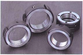
GLO-YS Precision Lock Nut
Reliable precision and high quality
Squareness of cutting surface: 0.005mm
Flatness of cutting surface: ≈100%
(contact surface with bearing body)
Locking Metal Material: Phosphor Bronze (High Wear Resistance)
Body Material: SCM440
Thread accuracy: ISO 4H
Hardness: HRC28°~32°
Main applications
Tightening nuts for bearings for machine tool spindles.
Tightening nut for ball screw support bearings.
Tightening nuts that require precision or where you want to reduce adjustment time.
How to install and remove
For installation, after cleaning the external thread, first set the lock nut. Then, to prevent loosening, loosen the 3 anti-loosening set screws attached to the nut 0.5~1 times. After that, tighten the first set screw until it stops lightly, then tighten the second and third screws sequentially at the specified tightening torque, and then the first set screw The installation is completed by tightening at the same specified torque.
To remove it, first loosen the three set screws sufficiently. At this point, the locking metal at the end of the set screw engages with the thread Since it is in a state, tap it lightly with a hammer from the side, make sure that the locking metal is free, and loosen the lock nut.
Thread Accuracy
The GLO M-YSA/M-YSR/M-YSF type lock nuts are finished in ISO 4H rating. Therefore, we ask that the screw accuracy of the shaft be finished to 4H grade. As a result, there is no need for post-integration adjustments, and high accuracy is maintained.
Precision Lock Nut Technical Data
The GLO-YS precision lock nut series meets all your precision lock nut requirements.
Please feel free to send us your quotation instructions.
□ Specification of thread tolerance range □ Left-hand thread processing □ Polishing of both end faces □ balancing hole processing
□ coating treatment (nickel plating treatment) □ width cutting (H size) □ Variant model number
□ Manufacture of precision lock nuts based on your drawings
Browse YS Series, M Series, and SYS Series Catalogs
M-YSA
M-YSR
M-YSF
Description
The M-YSA lock nut is a method of tightening the shaft from three points in the axial direction (axial direction). It is suitable for environments that require special assembly work.
Table of Principal Dimensions
Item No. Price (JPY) D h g t d n X m MAX. Nm
GLO M-YSA M14X1.5 2600 30 14 4 2 25 2-M4 2.2
GLO M-YSA M15X1 2600 30 14 4 2 25 2-M4 2.2
GLO M-YSA M16X1.5 2600 30 14 4 2 25 2-M4 2.2
GLO M-YSA M17X1 2600 32 16 4 2 27 2-M4 2.2
GLO M-YSA M18X1.5 2600 32 16 4 2 27 2-M4 2.2
GLO M-YSA M20X1 2600 38 16 4 2 33 3-M4 2.2
GLO M-YSA M20X1.5 2600 38 16 4 2 33 3-M4 2.2
GLO M-YSA M22X1.5 2830 38 16 4 2 33 3-M4 2.2
GLO M-YSA M24X1.5 2830 38 18 5 2 33 3-M4 2.2
GLO M-YSA M25X1.5 2830 38 18 5 2 33 3-M4 2.2
GLO M-YSA M27X1.5 3160 40 18 5 2 35 3-M4 2.2
GLO M-YSA M30X1.5 3160 45 18 5 2 40 3-M4 2.2
GLO M-YSA M33X1.5 3510 50 18 5 2 45 3-M4 2.2
GLO M-YSA M35X1.5 3510 52 18 5 2 47 3-M6 8.0
GLO M-YSA M36X1.5 3830 52 18 5 2 47 3-M6 8.0
GLO M-YSA M39X1.5 3830 58 20 6 2.5 52 3-M6 8.0
GLO M-YSA M40X1.5 3830 58 20 6 2.5 52 3-M6 8.0
GLO M-YSA M42X1.5 4120 62 20 6 2.5 56 3-M6 8.0
GLO M-YSA M45X1.5 4120 65 20 6 2.5 59 3-M6 8.0
GLO M-YSA M48X1.5 4640 70 20 6 2.5 64 3-M6 8.0
GLO M-YSA M50X1.5 4640 70 20 6 2.5 64 3-M6 8.0
GLO M-YSA M52X1.5 4990 73 22 7 3 66 3-M6 8.0
GLO M-YSA M55X2 4990 75 22 7 3 68 3-M6 8.0
GLO M-YSA M56X2 5440 75 22 7 3 68 3-M6 8.0
GLO M-YSA M60X2 5440 80 22 7 3 73 3-M6 8.0
GLO M-YSA M64X2 6250 85 22 7 3 78 3-M6 8.0
GLO M-YSA M65X2 6250 85 22 7 3 78 3-M6 8.0
GLO M-YSA M68X2 7200 92 24 8 3.5 84 3-M8 18.0
GLO M-YSA M70X2 7200 92 24 8 3.5 84 3-M8 18.0
GLO M-YSA M72X2 8030 94 24 8 3.5 86 3-M8 18.0
GLO M-YSA M75X2 8030 98 24 8 3.5 90 3-M8 18.0
GLO M-YSA M76X2 9030 98 24 8 3.5 90 3-M8 18.0
GLO M-YSA M80X2 9030 105 24 8 3.5 96 3-M8 18.0
GLO M-YSA M85X2 9800 110 24 8 3.5 102 3-M8 18.0
GLO M-YSA M90X2 10700 120 26 10 4 108 3-M8 18.0
GLO M-YSA M95X2 11300 125 26 10 4 113 3-M8 18.0
GLO M-YSA M100X2 12000 130 26 10 4 118 3-M8 18.0
GLO M-YSA M105X2 13000 140 28 12 5 125 3-M8 18.0
GLO M-YSA M110X2 14200 145 28 12 5 132 3-M8 18.0
GLO M-YSA M115X2 15300 150 28 12 5 137 3-M8 18.0
GLO M-YSA M120X2 16500 155 30 12 5 142 3-M8 18.0
GLO M-YSA M125X2 17600 160 30 12 5 147 3-M8 18.0
GLO M-YSA M130X2 18800 165 30 12 5 152 3-M8 18.0
GLO M-YSA M135X2 21000 175 32 14 6 160 3-M10 35.0
GLO M-YSA M140X2 22000 180 32 14 6 165 3-M10 35.0
GLO M-YSA M145X2 23100 190 32 14 6 175 3-M10 35.0
GLO M-YSA M150X2 24300 195 32 14 6 180 3-M10 35.0
GLO M-YSA M155X3 25500 200 34 16 7 180 3-M10 35.0
GLO M-YSA M160X3 26700 210 34 16 7 190 3-M10 35.0
GLO M-YSA M165X3 27900 210 34 16 7 190 3-M10 35.0
GLO M-YSA M170X2 29100 220 34 16 7 200 3-M10 35.0
GLO M-YSA M180X3 31500 230 36 18 8 205 3-M12 60.0
GLO M-YSA M190X3 33000 240 36 18 8 215 3-M12 60.0
GLO M-YSA M200X3 35000 250 38 18 8 225 3-M12 60.0
Note: 1 Nm = 10.2 kgf.cm