

High Speed Rotation SGL Series
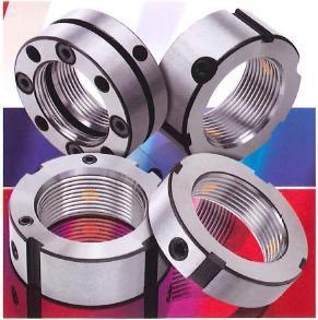
GLO-YS Precision Lock Nut
Reliable precision and high quality
Squareness of polished surface: 0.002mm
Flatness of polished surface: ≈100%
(contact surface with bearing body)
Locking Metal Material: Phosphor Bronze (High Wear Resistance)
Body Material: SCM440
Thread accuracy: ISO 4H
Hardness: HRC28°~32°
Concurrency: 0.002mm
Concentricity: 0.005mm
Main applications
Spindles for high-speed rotation where high precision is required
How to install and remove
How to install and remove SGL-F, SGL-R, SGL-A
For installation, after cleaning the external thread, first set the lock nut. Then, to prevent loosening, loosen the 3 anti-loosening set screws attached to the nut 0.5~1 times. After that, tighten the first set screw until it stops lightly, then tighten the second and third screws sequentially at the specified tightening torque, and then the first set screw The installation is completed by tightening at the same specified torque.
To remove it, first loosen the three set screws sufficiently. At this point, the locking metal at the end of the set screw engages with the thread Since it is in a state, tap it lightly with a hammer from the side, make sure that the locking metal is free, and loosen the lock nut.
How to install and remove SGL-K
After cleaning the external screw, set the YSK lock nut with the tightening bolt loosened. Tighten the tightening bolt diagonally and evenly with a gap of 1~2mm between the end face of the YSK lock nut and the end face of the mating side. Eliminate screw play. After that, loosen the tightening bolt evenly little by little until the YSK lock nut can be turned without rattling. Next, temporarily tighten with an axial force of 2~3 times the required axial force. This is a necessary step for the initial familiarization of YSK lock nuts. Then, loosen the YSK lock nut and retighten it until the proper axial force is obtained. Finally, tighten the 4~8 tightening bolts at right angles and evenly with the appropriate torque to ensure that they are completely fixed with the external screws.
To remove, loosen all set screws sufficiently before loosening the lock nut.
Thread Accuracy
The GLO SGL-F/SGL-R/SGL-A/SGL-K type lock nuts are finished in ISO 4H rating. Therefore, we ask that the screw accuracy of the shaft be finished to 4H grade. As a result, there is no need for post-integration adjustments, and high accuracy is maintained.
Precision Lock Nut Technical Data
The GLO-YS precision lock nut series meets all your precision lock nut requirements.
Please feel free to send us your quotation instructions.
□ Specification of thread tolerance range □ Left-hand thread processing □ Polishing of both end faces □ balancing hole processing
□ coating treatment (nickel plating treatment) □ width cutting (H size) □ Variant model number
□ Manufacture of precision lock nuts based on your drawings
Browse SGL Series Catalogs
SGL-F
SGL-R
SGL-A
SGL-K
Description
The SGL-F lock nut is designed to tighten the shaft from three points in the direction at an angle (30 degrees) to the thread. This excellent tightening method provides a high loosening torque and has a very high anti-loosening effect. In addition, this lock nut is ground all over the surface, including the internal thread. Therefore, it is ideal for spindles for high-speed rotation that require high precision.
Table of Principal Dimensions
Item No. D h d n x g/b t m MAX. Nm
SGL-F M14 x 1.5 30 14 25 3 x 4 2 M5 4.5
SGL-F M15 x 1 30 14 25 3 x 4 2 M5 4.5
SGL-F M16 x 1.5 30 14 25 3 x 4 2 M5 4.5
SGL-F M17 x 1 32 16 27 3 x 4 2 M5 4.5
SGL-F M18 x 1.5 32 16 27 3 x 4 2 M5 4.5
SGL-F M20 x 1 38 16 33 3 x 4 2 M6 8.0
SGL-F M20 x 1.5 38 16 33 3 x 4 2 M6 8.0
SGL-F M22 x 1.5 38 16 33 3 x 4 2 M6 8.0
SGL-F M24 x 1.5 38 18 33 3 x 5 2 M6 8.0
SGL-F M25 x 1.5 38 18 33 3 x 5 2 M6 8.0
SGL-F M27 x 1.5 40 18 35 3 x 5 2 M6 8.0
SGL-F M30 x 1.5 45 18 40 3 x 5 2 M6 8.0
SGL-F M33 x 1.5 50 18 45 3 x 5 2 M6 8.0
SGL-F M35 x 1.5 52 18 47 3 x 5 2 M8 18.0
SGL-F M36 x 1.5 52 18 47 3 x 5 2 M8 18.0
SGL-F M39 x 1.5 58 20 52 3 x 6 2.5 M8 18.0
SGL-F M40 x 1.5 58 20 52 3 x 6 2.5 M8 18.0
SGL-F M42 x 1.5 62 20 56 3 x 6 2.5 M8 18.0
SGL-F M45 x 1.5 65 20 59 3 x 6 2.5 M8 18.0
SGL-F M48 x 1.5 70 20 64 3 x 6 2.5 M8 18.0
SGL-F M50 x 1.5 70 20 64 3 x 6 2.5 M8 18.0
SGL-F M52 x 1.5 73 22 66 3 x 7 3 M8 18.0
SGL-F M55 x 2 75 22 68 3 x 7 3 M8 18.0
SGL-F M56 x 2 75 22 68 3 x 7 3 M8 18.0
SGL-F M60 x 2 80 22 73 3 x 7 3 M8 18.0
SGL-F M64 x 2 85 22 78 3 x 7 3 M8 18.0
SGL-F M65 x 2 85 22 78 3 x 7 3 M8 18.0
SGL-F M68 x 2 92 24 84 3 x 8 3.5 M8 18.0
SGL-F M70 x 2 92 24 84 3 x 8 3.5 M8 18.0
SGL-F M72 x 2 94 24 86 3 x 8 3.5 M8 18.0
SGL-F M75 x 2 98 24 90 3 x 8 3.5 M8 18.0
SGL-F M76 x 2 98 24 90 3 x 8 3.5 M8 18.0
SGL-F M80 x 2 105 24 96 3 x 8 3.5 M8 18.0
SGL-F M85 x 2 110 24 102 6 x 8 3.5 M8 18.0
SGL-F M90 x 2 120 26 108 6 x 10 4 M8 18.0
SGL-F M95 x 2 125 26 113 6 x 10 4 M8 18.0
SGL-F M100 x 2 130 26 118 6 x 10 4 M8 18.0
SGL-F M105 x 2 140 28 125 6 x 10 4 M10 35.0
SGL-F M110 x 2 145 28 132 6 x 10 4 M10 35.0
SGL-F M115 x 2 150 28 137 6 x 10 4 M10 35.0
SGL-F M120 x 2 155 30 142 6 x 12 5 M10 35.0
SGL-F M125 x 2 160 30 147 6 x 12 5 M10 35.0
SGL-F M130 x 2 165 30 152 6 x 12 5 M10 35.0
SGL-F M135 x 2 175 32 160 6 x 12 5 M10 35.0
SGL-F M140 x 2 180 32 165 6 x 12 5 M10 35.0
SGL-F M145 x 2 190 32 175 6 x 12 5 M10 35.0
SGL-F M150 x 2 195 32 180 6 x 12 5 M10 35.0
SGL-F M155 x 3 200 34 180 6 x 14 6 M10 35.0
SGL-F M160 x 3 210 34 190 6 x 14 6 M10 35.0
SGL-F M165 x 3 210 34 190 6 x 14 6 M10 35.0
SGL-F M170 x 3 220 34 200 6 x 14 6 M10 35.0
SGL-F M180 x 3 230 36 205 6 x 16 7 M12 60.0
SGL-F M190 x 3 240 36 215 6 x 16 7 M12 60.0
SGL-F M200 x 3 250 38 225 6 x 16 7 M12 60.0
*Note: (1) This data is for reference only. (2)1Nm=10.2kgf.cm=0.73lb.ft