

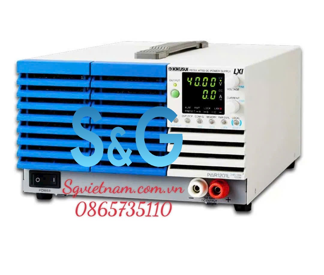
| Item/Model | PWR1201L | PWR1201ML | PWR1201MH | PWR1201H | |
|---|---|---|---|---|---|
| Nominal input rating | 100 Vac to 240 Vac, 50 Hz to 60 Hz, single phase | ||||
| Input voltage range | 85 Vac to 265 Vac | ||||
| Input frequency range | 47 Hz to 63 Hz | ||||
| Current (TYP) *1 | 100 Vac | 16.8 A | |||
| 200 Vac | 8.4 A | ||||
| Inrush current | 75 A or less | ||||
| Power (MAX) *2 | 1680 VA | ||||
| Power factor (TYP) *1 | 0.99 (input voltage: 100 V), 0.97 (input voltage: 200 V) | ||||
| Efficiency (TYP) *1 | 75 % | ||||
| Output hold time *2 | 20 ms or more | ||||
*1. At the rated output power for the rated output current. *2. 100 Vac, at the rated output power.
Output
| Item/Model | PWR1201L | PWR1201ML | PWR1201MH | PWR1201H | ||
|---|---|---|---|---|---|---|
| Rating | Output voltage *1 | 40 V | 80 V | 240 V | 650 V | |
| Output current *1 | 120 A | 60 A | 15.0 A | 5.55 A | ||
| Output power | 1200 W | |||||
| Voltage | Maximum settable voltage *2 | 42 V | 84 V | 252 V | 682.5 V | |
| Accuracy | ±(0.05 % of setting +0.05 % of rating) | |||||
| Resolution | 200 mV | 400 mV | 1000 mV | 2500 mV | ||
| Using FINE, OUT OFF | 10 mV | 10 mV | 100 mV | 100 mV | ||
| Using FINE, OUT ON | 1 mV | 1 mV | 10 mV | 10 mV | ||
| When using a communication interface | 0.1 mV | 0.1 mV | 0.1 mV | 0.1 mV | ||
| Line regulation *3 | ± 6 mV | ± 10 mV | ± 26 mV | ± 67 mV | ||
| Load regulation *4 | ± 6 mV | ± 10 mV | ± 26 mV | ± 67 mV | ||
| Transient response *5 | 1 ms or less | 2 ms or less | 2 ms or less | 3 ms or less | ||
| Ripple noise *6 | p-p *7 | 50 mV | 50 mV | 100 mV | 300 mV | |
| rms *8 | 5 mV | 5 mV | 20 mV | 50 mV | ||
| Rise time | At full load | 50 ms or less | 100 ms or less | |||
| No load | 50 ms or less | 100 ms or less | ||||
| Fall time *9 | At full load | 50 ms or less | 150 ms | 250 ms | ||
| No load | 500 ms or less | 1200 ms | 2000 ms | |||
| Maximum remote sensing compen- sation voltage (single line) | 1.5 V | 4 V | 5 V | 5 V | ||
| Temperature coefficient *10 | 100 ppm/ ℃ | |||||
| Current | Maximum settable current *2 | 126 A | 63 A | 15.75 A | 5.8275 A | |
| Setting accuracy *11 | ±(0.5 % of setting +0.1 % of rating) | |||||
| Resolution | 600 mA | 300 mA | 60 mA | 30 mA | ||
| Using FINE, OUT OFF | 100 mA | 10 mA | 10mA | 1 mA | ||
| Using FINE, OUT ON | 10 mA | 1 mA | 1 mA | 0.1 mA | ||
| When using a communication interface | 0.1 mA | 0.1 mA | 0.1 mA | 0.1 mA | ||
| Power fluctuation | ± 14 mA | ± 8 mA | ± 3.5 mA | ± 2.6 mA | ||
| Load variation | ± 29 mA | ± 17 mA | ± 8.0 mA | ± 6.1 mA | ||
| Ripple noise *12 | rms *8 | 240 mA | 120 mA | 36 mA | 18 mA | |
| Rise time (TYP) | At full load | 50 ms | 100 ms | |||
| Fall time (TYP) | At full load | 50 ms | 100 ms | |||
| Temperature coefficient *10 | 100 ppm/ ℃ | |||||
| Maximum internal resistance that can be set | 0.333 Ω | 1.333 Ω | 12.00 Ω | 87.84 Ω | ||
*1 The maximum output voltage and maximum output current are limited by the maximum output power. *2 Can be limited to approximately 95 % of the OVP trip point or OCP trip point. *3 85 Vac to 135 Vac or 170 Vac to 265 Vac, fixed load. *4 The amount of change that occurs when the load is changed from no load to full load (rated output power/rated output voltage) with rated output voltage. The value is measured at the sensing point. *5 The amount of time required for the output voltage to return to a value within “rated output voltage ± (0.1 % +10 mV).” The load current fluctuation is 50 % to 100 % of the maximum current with the set output voltage. *6 Measured using an RC-9131C probe that conforms to the JEITA specifications. At the rated output current. *7 When the measurement frequency bandwidth is 10 Hz to 20 MHz. *8 When the measurement frequency bandwidth is 10 Hz to 1 MHz. *9 When the bleeder circuit is set to bleeder normal. *10 When the ambient temperature is within 0°C and 50 °C. *11 Applies to the range of 1 % to 100 % of the rated current. TYP (0.1 % of rating) for 0 % to 1 %. *12 When the output voltage is 10 % to 100 % of the rating. At the rated output current.
Display function
| Item/Model | PWR1201L | PWR1201ML | PWR1201MH | PWR1201H | |
|---|---|---|---|---|---|
| Voltage display | Maximum display | 99.99 | 999.9 | ||
| Display accuracy | ± (0.2 % of reading +5 digits) | ||||
| Current display | Maximum display | 999.9 | 99.99 | 9.999 | |
| Display accuracy | ± (0.5 % of reading +8 digits) | ||||
| Power display | The PWR DSPL LED lights in red. | ||||
| Maximum display | 9999 | ||||
| Display accuracy | Displays the result of multiplying the current and voltage. The display is toggled with the voltage or current display. | ||||
Unless specified otherwise, the specifications are for the following settings and conditions.
Loads are pure resistive loads. ●The product is warmed up for at least 30 minutes (with current flowing). ●After warm-up, the product must be calibrated correctly in a 23 °C ± 5 °C environment according to the appropriate calibration procedure. ●Values indicated by “TYP” are typical values. They are not guaranteed performance values. ●Values indicated by “rating” are ratings. ●Values indicated by “reading” are readings. ●Values indicated by “f.s.” are full scale values. ●The PWR-01 operates over a wide range of output voltage and output current within rated output power. However, the current that can be output with rated output voltage and the voltage that can be output with rated output current are limited by the rated output power. ●The current that can be output with rated output voltage and the voltage that can be output with rated output current are as follows. Maximum output current with rated output voltage = Rated output power/ rated output voltage. Maximum output voltage with rated output current = Rated output power/ rated output current. ●Rated load and no load are defined as follows:In constant-voltage mode (when the output current is set to a value greater than or equal to the maximum output current with rated output voltage) Rated load: Refers to a resistive load that, when the rated output voltage is applied,makes the flowing current 95 % to 100 % of the maximum output current with rated output voltage.No load:Refers to a load through which no output current flows. In other words,refers to an open load (no load being connected). In constant-current mode (when the output voltage is set to a value greater than or equal to the maximum output voltage with rated output current) Rated load:Refers to a resistive load that, when the rated output current flows, makes the voltage drop to 95 % to 100 % of the maximum output voltage with rated output current. Including the voltage drop in the load cables, the PWR-01 output voltage must not exceed the maximum output voltage with rated output current. No load:Refers to a resistive load that, when the rated output current flows, makes the voltage drop to 10 % of the maximum output voltage with rated output current or 1 V whichever is higher. ●The specifications of the PWR-01 apply to the rear-panel output terminals.


