


Features
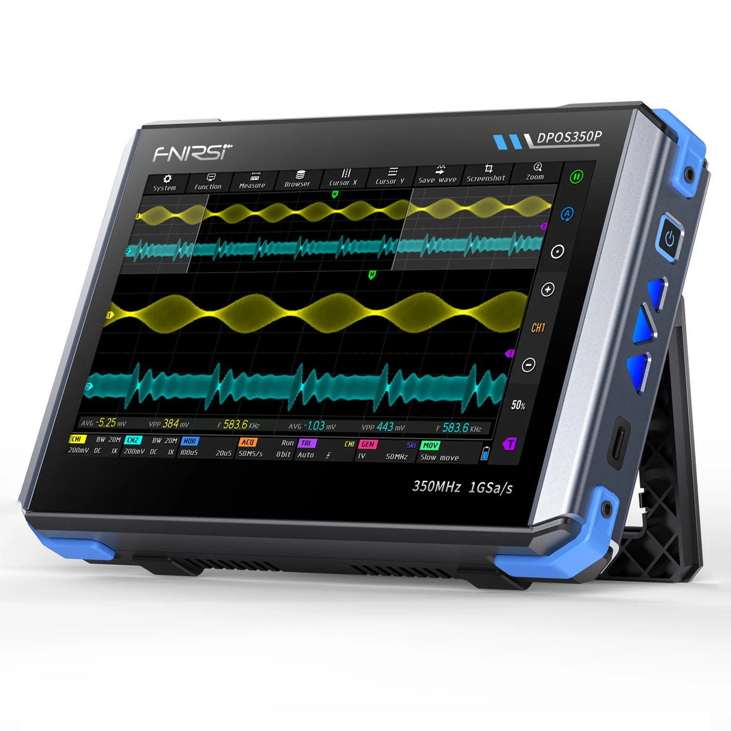
- Powerful multi-function integration: The DPOS350P combines a 350MHz oscilloscope, 50MHz signal generator, 200K~350MHz spectrum analyzer, and a 50MHz frequency response analyzer to meet various signal testing needs.
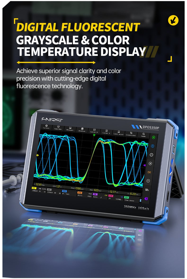
- High-performance waveform capture: With a 1GSPS real-time sampling rate, 350MHz analog bandwidth (single-channel mode), and an ultra-high 50,000 wfm/s waveform refresh rate, it can accurately capture and display low-probability anomaly signals.
- Fine display and operation: Equipped with a 7-inch 1024×600 high-resolution IPS touchscreen, it provides clear waveform display and supports grayscale and color temperature mode switching, making it easy to operate in different testing environments.
- Rich signal generation and analysis capabilities: The built-in 50MHz signal generator supports 14 standard waveforms and custom waveform functionality, while the spectrum analyzer covers a frequency range of 200K~350MHz, ideal for EMI, RF, and high-frequency signal testing.
- High-voltage protection and fast charging: The device has a high-voltage protection design up to 400V for safety, and with QC18W fast charging technology, it can be fully charged in 2 hours, ensuring long-term stable operation.
- Convenient data storage and export: It supports up to 500 waveform data storage and 90 image storage, and has USB data export functionality for easy analysis and report generation.
Specifications
Basic Parameters:
Brand
FNIRSI
Model
DPOS350P
Power-on configuration
5 preset items
Charging requirements
QC18W – 12V/1.5A (Type-C)
Languages
Chinese / English / Russian / Portuguese
Battery specifications
3.7V, 8000mAh lithium battery
Screen size
7 inches
Standby time
about 3 hours
Screen resolution
1024 x 600 pixels
Charging time
Startup ≈ 5 Hours
Screen technology
IPS full viewing angle
Total power consumption
10W
Interaction mode
capacitive touch screen
Heat dissipation
air cooling
Expansion interface
capacitive touch screen
Dimensions
190mm*128mm*37mm
Automatic shutdown
15 minutes ~ 1 hour / off
Firmware upgrade
support .iso image upgrade
Storage Temperature Range
-20~60℃
Oscilloscope Parameters:
Analog Channels
2
Analog bandwidth
350MHz
Rise time
1nS
Max sampling rate
1GSPS
Memory depth
60Kpts
Input impedance
1MΩ / 14PF
Time base range
5nS ~ 50S
Roll time base
50mS ~ 50S
Vertical sensitivity
2mV ~ 20V(1X)
Vertical range
16mV ~ 160V(1X)
DC accuracy
±2%
Time accuracy
±0.01%
Input coupling
DC / AC
Probe attenuation
1X / 10X / 100X
Hardware bandwidth limit
150M / 20M
High resolution mode
8bit ~ 16bit
Parameter measurements
12 types
Cursor measurement
time, period, frequency, level, voltage
Trigger detection
digital trigger
Trigger channel
CH1 / CH2
Trigger mode
Auto / Single / Normal
Trigger edge
rising edge / falling edge
Trigger suppression
L1 ~ L3
Trigger level
manual / automatic 10% ~ 90%
Screenshot storage
90 pictures
Waveform storage
500 groups
Background grid
display / hide
Waveform movement
coarse adjustment / fine adjustment
Overvoltage protection
withstand voltage 400V
Waveform brightness
adjustable
Simple FFT display
support
Digital fluorescence
support
Color temperature display
support
X-Y mode
support
ZOOM time base
support
One-key automatic adjustment
support
One-key return to zero
support
Data browser
support
Signal Generator Parameters:
Waveform types
14 standard functions + captured waveform
Frequency
0 ~ 50MHz(sine wave only, other waveforms up to 10M/5M/3M)
Amplitude
0 ~ 5VPP
Offset
-2.5V ~ +2.5V
Duty cycle
0.1% ~ 99.9%
Frequency resolution
1Hz
Amplitude resolution
1mV
Offset resolution
1mV
Duty cycle resolution
0.1%
Customizable captured waveform
500 groups
Frequency Response Analyzer Section:
Excitation signal frequency
100Hz ~ 50MHz
Excitation signal amplitude
0 ~ 5VPP
Excitation signal offset
-2.5V ~ +2.5V
Excitation frequency count
20 ~ 500
Cursor measurement
frequency / gain / phase
Operating mode
single / cyclic
System calibration
support
Spectrum Analyzer Part:
Conversion method
FFT
FFT length
4K ~ 32K
Frequency range
200KHz ~ 350MHz
Level range
-60dBmV ~ +260dBmV
Cursor measurement
frequency / amplitude
Marking parameter
maximum energy harmonic
Waterfall chart
support
3D waterfall chart
support
Automatic adjustment
support
System calibration
support
⚠ Special Precautions
- When using both channels simultaneously, the ground clips of both probes must be connected together. It is strictly prohibited to connect the ground clips of the two probes to different potentials, especially to different potential ends of high-power equipment or 220V/110V circuits. Doing so may damage the oscilloscope’s mainboard because both channels share a common ground, and connecting them to different potentials can cause a ground loop and short-circuit the mainboard.
- The BNC input on the oscilloscope has a maximum tolerance of 400V. It is strictly forbidden to input voltages exceeding 400V when the 1X probe switch is used.
- For charging, use the dedicated charger provided. It is prohibited to use the power supply of other equipment under test or a USB connection. Doing so may cause a ground loop and short-circuit the oscilloscope’s mainboard, potentially damaging it during the testing process.
- When measuring high-frequency, high-voltage signals, use a 100X probe (e.g., for ultrasonic welders, ultrasonic cleaners, etc.), or even a 1000X probe (e.g., for the high-voltage side of high-frequency transformers, induction heating coil resonators, etc.).