
ylinder With Lock, Double Acting, Single Rod MNB Series Specifications

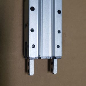
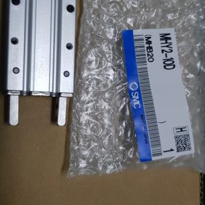
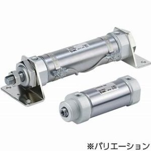
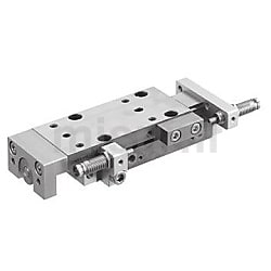
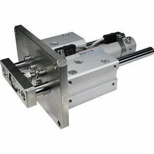
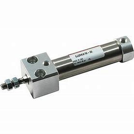
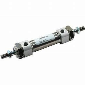
Cylinder With Lock, Double Acting, Single Rod MNB Series external appearance
| Tube Internal Diameter (mm) | 16 |
|---|---|
| Action | Double acting, single rod |
| Lubrication | Not required (non-lubricated) |
| Locking Method | Spring lock (exhaust locking) Pneumatic (pressurized locking) Spring/pneumatic combination lock |
| Fluid | Air |
| Proof Pressure | 1.05 MPa |
| Maximum operating pressure | 0.7 MPa |
| Minimum operating pressure | 0.08 MPa |
| Ambient and Fluid Temperature | Without auto switch: -10°C to 70°C (No freezing) With auto switch: -10°C to 60°C (No freezing) |
| Piston Speed | *50 to 500 mm/s |
| Cushioning | Rubber cushion |
| Stroke Length Tolerance | +1.0 0 |
| Mount Support Type | Basic type, axial foot type, rod-end flange type, double clevis type |
*Load restrictions exist depending upon piston speed when locked, mounting direction and operating pressure.
Lock Specifications
| Tube Inner Diameter (mm) | 32 | 40 | 50 | 63 | 80 | 100 |
|---|---|---|---|---|---|---|
| Locking Action | Spring locking (exhaust locking) | |||||
| Unlocking pressure | 0.25 MPa or more | |||||
| Locking Starting Pressure | 0.20 MPa or less | |||||
| Maximum Operating Pressure | 1.0 MPa | |||||
| Locking Direction | Bidirectional | |||||
| Holding Force (Maximum Static Load) N* | 552 | 882 | 1,370 | 2,160 | 3,430 | 5,390 |
*The holding force (maximum static load) indicates the maximum capacity, not the normal holding capacity. Therefore, be sure to select the cylinder upon checking the details in the SMC catalog.
Single Rod Weight Table / Aluminum Tube
(Unit: kg)
| Tube Inner Diameter (mm) | 32 | 40 | 50 | 63 | 80 | 100 | |
|---|---|---|---|---|---|---|---|
| Basic weight | Basic type | 1.20 | 1.72 | 2.76 | 4.06 | 6.85 | 10.26 |
| Foot type | 1.30 | 1.84 | 2.94 | 4.32 | 7.28 | 10.85 | |
| Flange type | 1.44 | 2.04 | 3.29 | 4.80 | 8.30 | 13.57 | |
| Single clevis | 1.45 | 1.98 | 3.10 | 4.69 | 7.96 | 13.43 | |
| Double clevis type | 1.46 | 1.99 | 3.19 | 4.85 | 8.25 | 13.95 | |
| Additional weight per 50 stroke | All mounting brackets | 0.11 | 0.16 | 0.26 | 0.27 | 0.42 | 0.56 |
| Accessories | Single knuckle joint | 0.15 | 0.23 | 0.26 | 0.26 | 0.60 | 0.83 |
| Double knuckle joint (with pin) | 0.22 | 0.37 | 0.43 | 0.43 | 0.87 | 1.27 | |
Calculation (Example) MNBB32-100-D (basic type, ø32 mm, 100 st)
- Basic weight: 1.20 kg (Basic type, ø32 mm)
- Additional weight: 0.11 kg / 50 stroke
- Cylinder stroke: 100 stroke
1.20 + 0.11 × 100/50 = 1.42 kg
Construction Principle Drawings
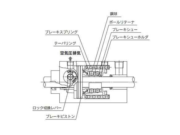
Construction principle drawing (locked state)
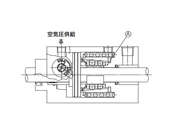
Construction principle drawing (unlocked state)
Spring lock (exhaust locking)
The spring force that acts on the taper ring is magnified by a wedge effect, and is conveyed to the numerous steel balls that are arranged in 2 rows. These act on the brake shoe holder and brake shoe, which locks the piston rod by tightening it using a large force.
Unlocking is accomplished when air pressure is supplied to the unlocking port. The brake piston and taper ring oppose the spring force, moving to the right side, and the ball retainer strikes cover section A. The braking force is released as the steel balls are moved away from the taper ring by the ball retainer.
Diagram
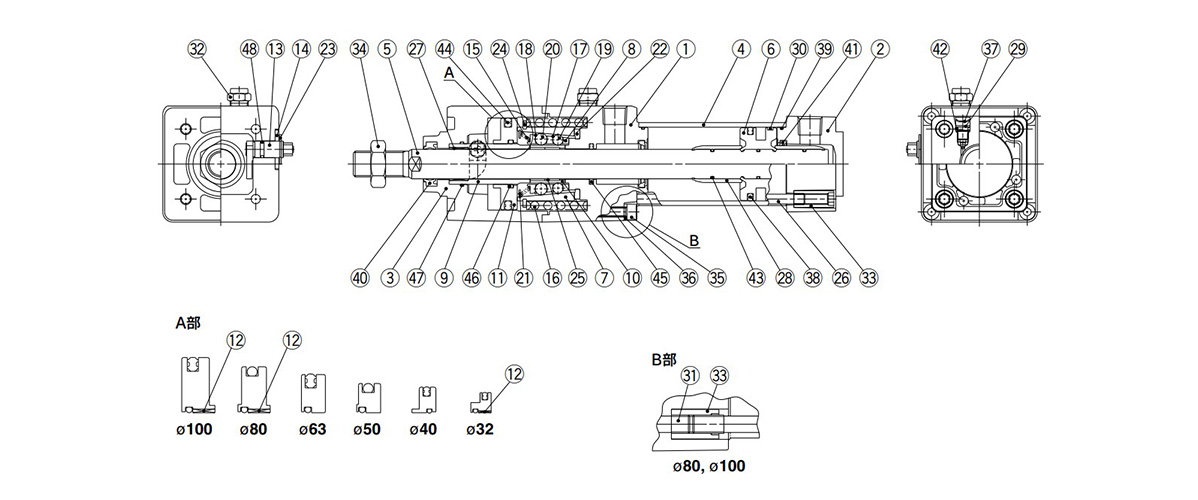
Cylinder With Lock, Double Acting, Single Rod MNB Series diagram
| Number | Part Name | Material | Notes | |
|---|---|---|---|---|
| 1 | Rod cover | Aluminum alloy | Hard anodized aluminum with metallic coating | |
| 2 | Head cover | Diecast aluminum | Chromate with metallic coating | |
| 3 | Cover | Aluminum alloy | Hard anodized aluminum with metallic coating | |
| 4 | Cylinder Tubing | Aluminum alloy | Hard anodized aluminum | |
| 5 | Piston rod | Carbon steel | Hard chrome plated | |
| 6 | Piston | Aluminum alloy | Chromate | |
| 7 | Taper Ring | Carbon steel | Heat treated | |
| 8 | Ball Retainer | Special resin | – | |
| 9 | Piston Guide | Carbon steel | Zinc chromate | |
| 10 | Brake Shoe Holder | Special steel | Heat treated | |
| 11 | Release Piston |
ø32 mm, ø80 mm, ø100 mm | Aluminum alloy | Chromate |
| ø40 mm, ø50 mm, ø63 mm | Hard anodized aluminum | |||
| 12 | Release Piston Bushing | Steel and special resin | ø32 mm, ø80 mm, ø100 mm only | |
| 13 | Unlocking Cam | Chrome molybdenum steel | Glossy chromate | |
| 14 | Washer | Carbon steel | Colorless zinc chromate | |
| 15 | Retainer Pre-Load Spring |
ø32 mm | Steel wire | Zinc chromate |
| ø40 to 100 mm | Stainless steel wire | – | ||
| 16 | Brake Spring | Steel wire | Zinc chromate | |
| 17 | Clip A | Stainless steel | – | |
| 18 | Clip B | Stainless steel | – | |
| 19 | Steel Ball A | Carbon steel | – | |
| 20 | Steel Ball B | Carbon steel | – | |
| 21 | Tooth Ring | Stainless steel | – | |
| 22 | Damper | Polyurethane rubber | – | |
| 23 | Type C Retaining Ring for Unlocking Cam Shaft | Carbon steel | – | |
| 24 | Type C Retaining Ring for Taper Ring | Carbon steel | – | |
| 25 | Brake Shoe | Special friction material | – | |
| 26 | Tie-Rod | Carbon steel | Zinc chromate | |
| 27 | Bushing | Resin/Copper alloy (Multiple layers) | – | |
| 28 | Cushion Ring | Aluminum alloy | Anodized aluminum | |
| 29 | Cushion Valve | Steel wire | – | |
| 30 | Wear Ring | Resin | – | |
| 31 | Unit Holding Tie-Rod | Carbon steel | Bright chromate ø80 mm and ø100 mm only | |
| 32 | BC Element | – | – | |
| 33 | Tie-Rod Nut | Carbon steel | – | |
| 34 | Rod End Nut | Carbon steel | – | |
| 35 | Hex Socket Head Cap Screw | Chrome molybdenum steel | ø32 to 63 mm | |
| 36 | Spring Washer for Hex Socket Head Cap Screw | Steel wire | ø32 to 63 mm | |
| 37 | Retaining Ring | Steel for spring | – | |
| 38 | Piston Seal | NBR | – | |
| 39 | Cylinder Tube Gasket | NBR | – | |
| 40 | Rod Seal A | NBR | – | |
| 41 | Cushion Seal | NBR | – | |
| 42 | Cushion Valve Seal | NBR | – | |
| 43 | Piston Gasket | NBR | – | |
| 44 | Release Piston Seal | NBR | – | |
| 45 | Rod Seal B | NBR | – | |
| 46 | Release Piston Gasket | NBR | – | |
| 47 | Piston Guide Gasket | NBR | – | |
| 48 | Unlocking Cam Gasket | NBR | – | |
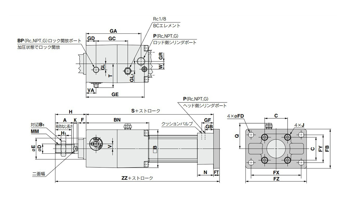
Dimensional drawing
(Units: mm)
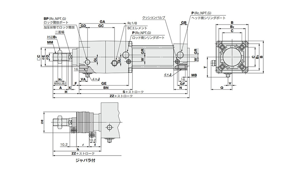
Basic type (B): MNBB dimensional drawing
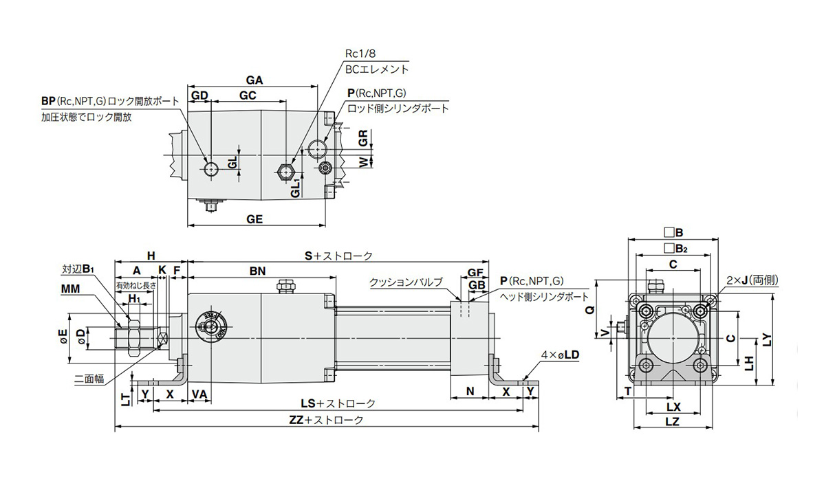
Axial foot type (L): MNBL dimensional drawing
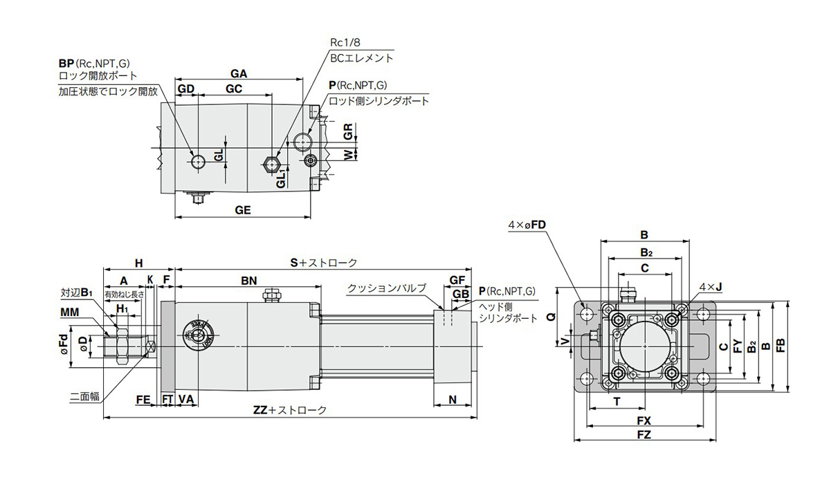
Rod-end flange type (F): MNBF dimensional drawing