XM3-110 electronic multimeter to be launched in
2025
download
Technical specs
Communication Specifications
Instruction manual
CAD Drawings
software
Product Description
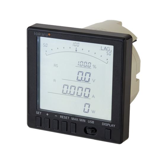
The XM2-110 electronic multimeter, which was launched in 2012, will be renewed to the XM3-110.
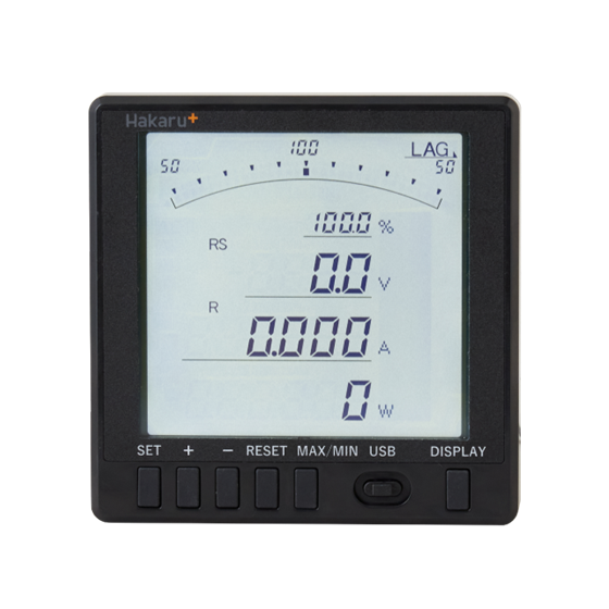
Introducing the XM3-110, which retains the functions of the XM2-110 and adds new functions to make it easier to handle.
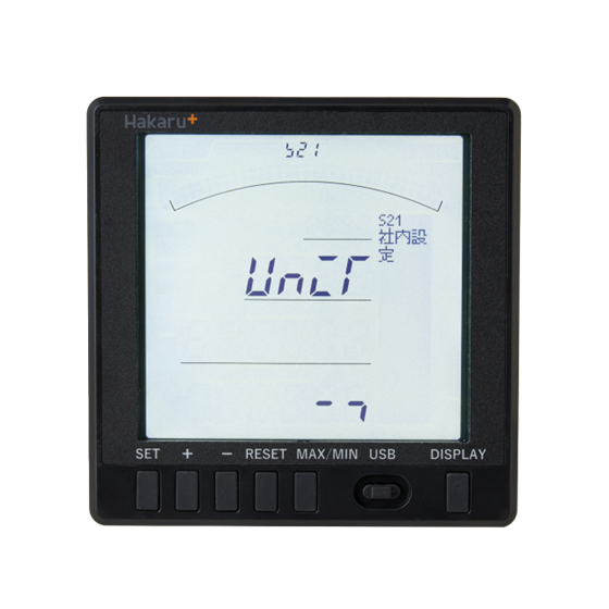
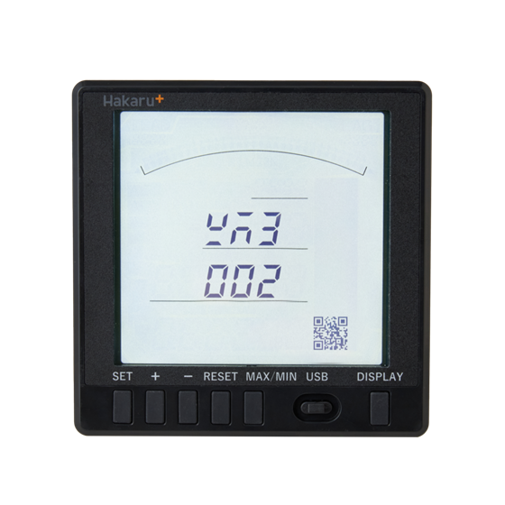
(The screen shown is under development)
forte
- Changed part of the screen to a full-dot area to display more information.
Since characters and symbols can be displayed, the setting contents are displayed during manual setting. - By scanning the QR code, you can check the device information such as specifications and model name. * Patented
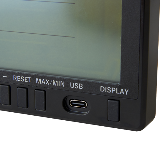
- THE CONNECTOR FOR PC SETTING HAS BEEN CHANGED TO USB TYPE-C, AND IT CAN NOW BE SET BY USB POWER SUPPLY.
- The shape of the switch part has been changed to make it easier to operate.
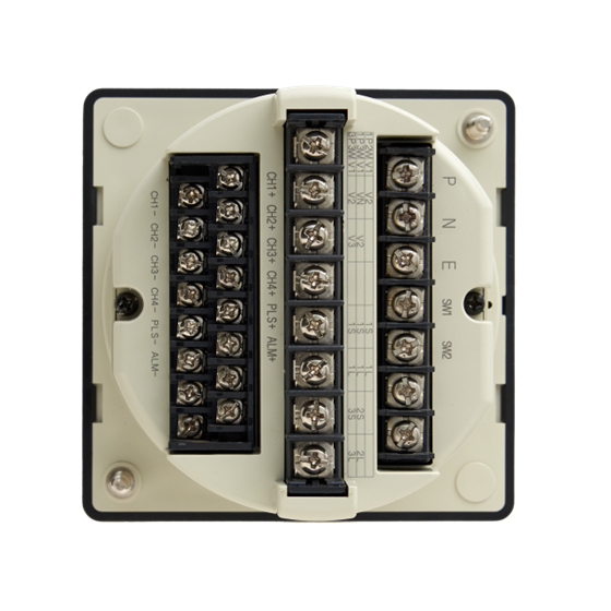
- In order to make it easier to see the terminal names and equipment numbers, the molding color of the
case body has been changed from black to ivory. - Harmonics that can be measured from the 15th to the 31st order are supported.
- We have standardized special products produced in the past.
- The backlight is now available in two colors: amber and white. (Green and orange are abolished)
specification
specification
| item | specification |
|---|---|
| Phase-wire | (Model designation) ・Single-phase 2-wire, single-phase 3-wire, 3-phase 3-wire (setting switching) ・Three-phase 4-wire |
| Voltage Input | ・AC110V, AC220V (setting switching) |
| Current Input | (Model designation) ・5A ・1A |
| Auxiliary power supply | (Model designation) ・AC85~264V or DC85~143V ・DC20~40V ・DC30~60V |
| External Operation Input | 2 points |
Digital display
| Measurement items (number of digits) | Input Rating | Intrinsic error | remarks |
|---|---|---|---|
| Current (3 & 4) | 0~1A・0~5A | ±0.5% | Display unit A / kA switching |
| Line voltage (3·4) | 0~150V・0~300V | ±0.5% | Display unit V / kV switching |
| Phase voltage (3·4) | 0~150√3V・0~300√3V | ±0.5% | Display unit V / kV switching |
| Power (4) | 0~1kW・-1~0~1kW・0~2kW・-2~0~2kW | ±0.5% | Display unit W, kW, MW switching, negative display |
| Reactive Power (4) | 0~Lag1kvar・Lead1~0~Lag1kvar・0~Lag2kvar・Lead2~0~Lag2kvar | ±0.5% | Display unit var, kvar, mvar switching, with lag and lead display |
| Power Factor (3) | Lead50~100~Lag50・Lead0~100~Lag0(%) | ±2.0% | With Lag and Lead, 1 decimal place |
| Power Quantity (6) | The digital display has a multiplier of × 1, ×10, ×100, ×1000 |
±2.0%
±2.5% |
5~120% of rated current (power factor=1) 10 ~120% |
| Reactive Power (6) | The digital display has a multiplier of × 1, ×10, ×100, ×1000 |
±2.5%
±2.5% ±3.0% |
10~120% of rated current (power factor=0) 20 ~120% 10% |
| Frequency (3) | 45~65Hz, 45~55Hz, 55~65Hz, | ±0.5% | 1 decimal place |
| Demand Current : Maximum Demand Current (3・4) |
0~5A | ±0.5% | Demand timed selection setting, heat conduction root calculation method |
| Demand Power Maximum Demand Power (4) |
0~1kW・0~2kW | ±0.5% | Demand timed selection setting, heat conduction root calculation method |
| Current Extension Measurement (3 & 4) | 0~5A・0~25A | ±8.0% | Display unit A / kA switching: 5-fold extension (R phase only) |
| Harmonic current (3 & 4) | Overall RMS: 0~1A・0~5A Total Distortion: |
±2.5% | Display unit A / kA switching, R phase and S phase only measurement, total rms value, total distortion rate, each rms value, each order distortion rate, fifth-order equivalent effective value, fifth-order equivalent distortion rate, distortion rate up to 50% |
| Harmonic voltage (3/4) | Overall RMS: 0~150V・0~300V Total distortion: |
±2.5% | Display unit V / kV switching, RS phase and ST phase only measurement, total rms value, total distortion rate, each rms value, each distortion rate, 5th equivalent rms value, 5th equivalent distortion rate, distortion rate up to 50% |
| Zero-phase voltage (3·4) Maximum
zero-phase voltage (3·4) |
EVT: 110 VAC / 190.5 VAC ZPD : |
±1.0% | |
| Io(4) | AC0.8A | ±1.0% | 表示単位A |
| Ior(4) | AC0.1A | ±10.0% | 表示単位A |
通信仕様
| 方式 | 項目 | 定格 |
|---|---|---|
| RS-485通信 | インターフェイス | RS-485 |
| 〃 | 伝送距離 | 1km以下(最大32台) |
| 〃 | 通信速度 | 1200・2400・4800・9600・19200bps |
| 〃 | 伝送ケーブル | シールド付より対線 (CPEV-S0.9φ) |
| 〃 | 終端抵抗 | 100Ω内蔵 (端子短絡で終端抵抗ON) |
| 〃 | Synchronization method | Asynchronous method |
| 〃 | Communication control method | Polling selection method (semi-double) |
| 〃 | Usage Code | ASCII |
| 〃 | Data method: Starbit | 1 bit |
| 〃 | Data method: Data | 7-bit |
| 〃 | Data method: Parity bit | even number |
| 〃 | Data method: Stop bits | 1 bit |
| RS-485 communication (Modbus) | interface | RS-485 communication (Modbus) |
| 〃 | Transmission distance | Less than 1 km (up to 32 cars) |
| 〃 | Transmission speed | 1200, 2400, 4800, 9600, 19200bps |
| 〃 | Transmission cable | Shielded stranded wire (recommended: CPEV-S0.9φ) |
| 〃 | Termination Resistor | Built-in 100Ω (Termination Resistor ON on Pin Short Circuit) |
| 〃 | Synchronization method | Asynchronous method |
| 〃 | Communication control method | Polling selection method (semi-double) |
| 〃 | Usage Code | RTU |
| 〃 | Data method: Starbit | 1 bit |
| 〃 | Data method: Data | 8-bit |
| 〃 | Data method: Parity bit | None or even or odd |
| 〃 | Data method: Stop bits | 1 or 2 bits |
| CC-Link communication | Communication Protocols | CC-Link Ver1.1 and Ver2 (8x mode) |
| 〃 | Transmission speed | 156k, 625k, 2.5M, 5M, 10Mbps |
| 〃 | Number of occupied stations | Remote Device Station: Occupies 1 station |
| 〃 | Configurable area code | 1~64 |
| 〃 | Number of connected devices | 42 units (when configured with this unit only) |
| 〃 | Word Area (CC-Link Ver1.1) |
4 words each for transmission and reception (for analog data) |
| 〃 | Word Area (CC-Link Ver2) |
32 words each for transmission and reception (for analog data) |
| 〃 | Bit Area (CC-Link Ver1.1) |
32 bits each for transmission and reception (for contact data) |
| 〃 | Bit Area (CC-Link Ver2) |
256 bits each for transmission and reception (for contact data) |
| Contact status input | Same as the auxiliary power supply (operates with energization for 0.3 seconds or more, continuous energization is possible) The maximum input current is 6 mA or less. |

