

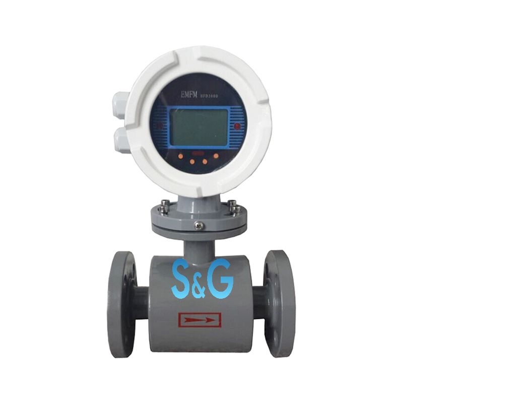
Product Description
■Quick Details
| Place of Origin |
Zhejiang China |
Output Signal |
4-20MA |
Connection |
Flange |
|
Model NO. |
LD Series |
Max Temp. |
120℃ |
Application |
Wastewater, agriculture, food and so on |
|
Medium |
Water, Air |
Customized Support |
OEM, ODM, OBM |
Protection Grade |
IP68 |
|
Accuracy |
±0.5% |
Brand Name |
ZYIA |
Sample |
Available |
■Measuring Principles
Measuring range of the LD smart electromagnetic flowmeter determined on the basis of Faraday Low of Electromagnetic Induction: If lines of magnetic induction are cut through in magnetic field by conductive liquid. Based on the law, we install a pair of electrodes on both sides inside a pipe that runs perpendicularly to both the measuring tube axes and magnetic line of force, electromotive E will be generated between the electrodes.
When flux needs measuring, conductive liquid is let go on velocity V through a magnetic field that is perpendicular to the flow direction. With the conductive liquid running through, a voltage that is proportional to average flowing velocity is to be induced. The voltage signal induced can be detected by two or more electrodes that contacts the liquid and then transmitted to converter for intellectual processing before being shown in LCD display outputting stand end signals of 4~20mA or 0-1kHz.
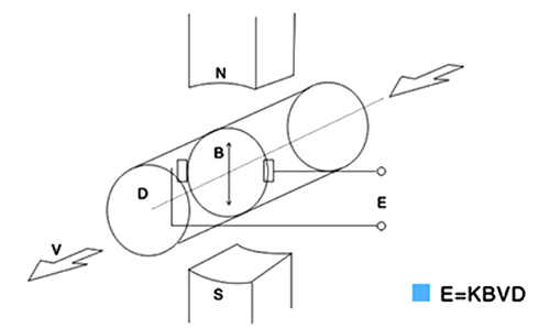 |
K—instrument modulus
B—density of magnetic induction V—average flowing velocity through a section in tube D—inner diameter of the tube |
■Features
● Various liner can be selected hat satisfies industrial applications
● Flow velocity range: 0-12m/s, with good results for low flow applications
● It comes any flanges such as, ANSI DIN JIS Etc
● It desirable for high pressure application
● Protection class: IP68 is available, and the sensor can sink into the water
● PFA Liner suitable in vacuum tube
● High accuracy of +/-0.5% of reading
● With Forward Reverse flowrate measure function
■Specification
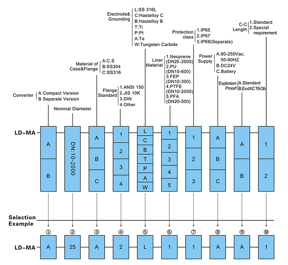
| Size | 10,15,20,25,32,40,50,65,80,100,125,150,200,250,300,350,400,450,500,600,700,800,900, 1000, 1200, 1400,1600, 1800,2000mm |
| Explosion Proorf | Ex d II C T6 Gb |
| Electrode & Grounding | Stainless Steel 316L
Hastelloy B Hastelloy C Titanium Tantalum Platinum Tungsten Carbide |
| Measuring Range | Velocity 0.3-15m/s min. |
■Material
| Measuring Tube | Stainless Steel 304
Stainless Steel 316 (Option) |
Cable Entry | 2XPG 11, 1/2 NPT (Option) |
| Flange | Carbon Steel (standard)
Stainless Steel 304 (Option) Stainless Steel 316 (Option) |
Ambient Temperature | -25 to +60 Deg.C |
| Coil Housing | Carbon Steel (standard)
Stainless Steel 304 (Option) Stainless Steel 316 (Option) |
Process Connection | Flange |
| Liner | Neoprene (25 2000mm)
Polyurethane (15 600mm) FEP (10-300mm) PTFE (10-2000mm) PFA (20-500mm) |
Flanges Type | JIS 10K1 JIS 20K/ JIS 40K ANSI 150# 1
ANSI 300# / ANSI 600# DIN PN 10/PN 16/ PN 25/ PN 40 |
| Protection | IP 68 (Submersible) | Grounding Resistance Must | be less than 100Ω |
| Conductivity | to be more than 5us/cm | Temperature | -20~ +80C (Neoprene)
-20~+60C (PU) -25~+120C (FEP) -30~+120C (PTFE) -30~+120C (PFA) |
| Working Pressure | 1.6Mpa (Size 10-150mm)
1.0Mpa (Size 200-900mm) 0.6Mpa (Size 1000-2000mm) |
■Flow Selection Table
| Caliber(mm) | Minimum Flow Options (m3/h) | Common choice of full scale flow range options (m3/h) |
| 10 | 0.10 | 0.4,0.5,0.6,0.8,1.0,1.2,1.6,2.0,2.5 |
| 15 | 0.20 | 1.0,1.2,1.6,2.0,2.5,3.0,4.0.5,0.60 |
| 20 | 0.35 | 2.0,2.5,3.0,4.0,5.0,6.0,8.0,10.0,12.0 |
| 25 | 0.55 | 3.0,4.0,5.0,6,0.8,0.10,0.12,0.14.0,16.0 |
| 32 | 1.0 | 5.0,6.0,8.0.,10.0,12,16,20,25 |
| 40 | 1.5 | 8.0,10.0,12,16,20,25,30,40 |
| 50 | 2.5 | 12,16,20,25,30,40,50,60,70 |
| 65 | 4.0 | 20,25,30,40,50,60,80,100,120 |
| 80 | 5.5 | 25,30,40,50,60,80,100,120,160 |
| 100 | 8.5 | 40,50,60,80,100,120,160,200,250 |
| 125 | 14 | 60,80,100,120,160,200,250,300,400,500,600 |
| 150 | 20 | 100,120,160,200,250,300,400,500,600 |
| 200 | 35 | 160,200,250,300,400,500,600,800,1000 |
| 250 | 55 | 200,250,300,400,500,600,800,1000,1200,1600 |
| 300 | 80 | 300,400,500,600,800,1000,1200,1600,2000,2500 |
| 350 | 105 | 400,500,600,800,1000,1200,1600,2000,2500,3000 |
| 400 | 135 | 500,600,800,1000,1200,1600,2000,2500,3000,4000 |
| 450 | 175 | 600,800,1000,1200,1600,2000,2500,3000,4000,5000 |
| 500 | 215 | 800,1000,1200,1600,2000,2500,3000,4000,5000,6000 |
| 600 | 305 | 1000,1200,1600,2000,2500,3000,4000,5000,6000,1000 |
| 700 | 415 | 1200,1600,2000,2500,3000,4000,5000,6000,10000,12000 |
| 800 | 545 | 1600,2000,2500,3000,4000,5000,6000,10000,12000,16000 |
| 900 | 690 | 2000,2500,3000,4000,5000,6000,10000,12000,16000,20000 |
| 1000 | 850 | 2500,3000,4000,5000,6000,10000,12000,16000,20000,25000 |
| 1200 | 1250 | 6000,10000,20000,30000,40000,50000 |
| 1400 | 1700 | 8000,10000,20000,30000,40000,50000 |
| 1600 | 2500 | 10000,20000,30000,40000,50000,65000 |
| 1800 | 3000 | 15000,20000,30000,40000,50000,60000,70000,80000 |
| 2000 | 3500 | 20000,40000,60000,80000,100000 |
| 2200 | 4000 | 20000,40000,60000,80000,100000,120000 |
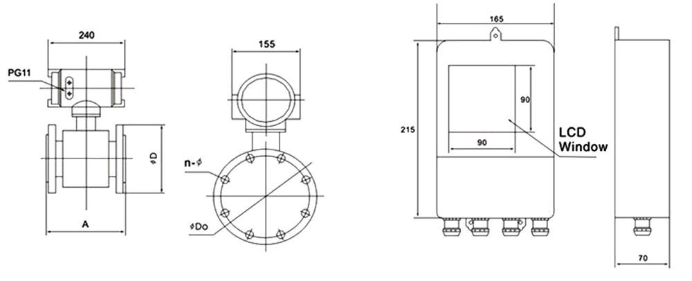
■Dimension (See diagram and drawing below)
| Diameter(mm) | A | D | DO | n-Ф |
| 10 | 200 | 90 | 60 | 4X14 |
| 15 | 200 | 95 | 65 | 4X14 |
| 20 | 200 | 105 | 75 | 4X14 |
| 25 | 200 | 115 | 85 | 4X14 |
| 32 | 200 | 140 | 100 | 4X18 |
| 40 | 200 | 150 | 110 | 4X18 |
| 50 | 200 | 165 | 125 | 4X18 |
| 65 | 250 | 175 | 145 | 8X18 |
| 80 | 250 | 200 | 160 | 8X18 |
| 100 | 250 | 220 | 180 | 8X18 |
| 125 | 250 | 250 | 210 | 8X18 |
| 150 | 300 | 285 | 240 | 8X22 |
| 200 | 350 | 340 | 295 | 8X22 |
| 250 | 400 | 395 | 350 | 12X22 |
| 300 | 460 | 445 | 400 | 12X22 |
| 350 | 460 | 505 | 460 | 16X26 |
| 400 | 600 | 565 | 515 | 16X26 |
| 450 | 600 | 615 | 565 | 20X26 |
| 500 | 600 | 670 | 620 | 20X26 |
| 600 | 600 | 780 | 725 | 20X30 |
| 700 | 600 | 895 | 840 | 20X30 |
| 800 | 800 | 1015 | 950 | 24X33 |
| 900 | 900 | 1115 | 1050 | 24X33 |
| 1000 | 1000 | 1230 | 1160 | 28X33 |
| 1200 | 1200 | 1405 | 1340 | 28×36 |
| 1400 | 1400 | 1630 | 1560 | 32X36 |
| 1600 | 1600 | 1830 | 1760 | 36X36 |
| 1800 | 1800 | 2045 | 1970 | 36X36 |
| 2000 | 2000 | 2265 | 2180 | 48X42 |
| 2200 | 2200 | 2405 | 2315 | 52X45 |
In order to enable a reliable flow meter, Pls note the following installation requirements:
1. As far as possible to avoid ferromagnetic objects and equipment with strong magnetic fields(big electric machine, big transformer) is protect of the magnetic field sensor.
2. lt should be installed in the ventilation in the dry, avoid moist and stagnant water.
3. lt should be avoided solarization and rain, To avoid environment temperature higher than 60℃ and humidity more than 95%
4. Flow meter should be enough space around for easy installation and Maintenance.
5. Flow meter must be installed at the outlet of the pump. valve should be installed at downstream of the flow meter.

