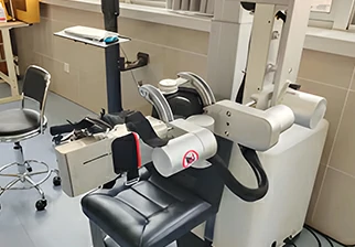
Product Description
The M series robot joint actuators include the outer diameter of 52mm 70mm 80mm 110mmmm , the maximum torque can reach 100Nm; With stable product performance, low price, which can meet the needs of many customers for joint modules. Widely used in CNC machine, automated production lines, robot arms, humanoid robots, large rotating platforms.
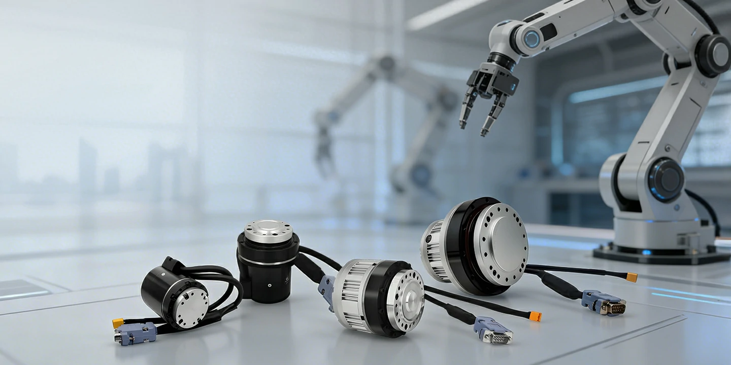
M series joint actuators quick selection table
| Model | M8025E25B50/80/100L | M8010E17B50/80/100L | M4215E14B50/80/100L | M4210E14B50/80/100L |
| Motor rated voltage | 36VDC±10% | 36VDC±10% | 36VDC±10% | 36VDC±10% |
| Output torque | 51NM/85NM/100NM | 34NM/35NM/51NM | 7NM/10NM/10NM | 3.2NM |
| Output Speed | 0~30RPM/0~18RPM/0~15RPM | 0~30RPM/0~18RPM/0~15RPM | 0~40RPM/0~25RPM/0~20RPM | 0~40RPM |
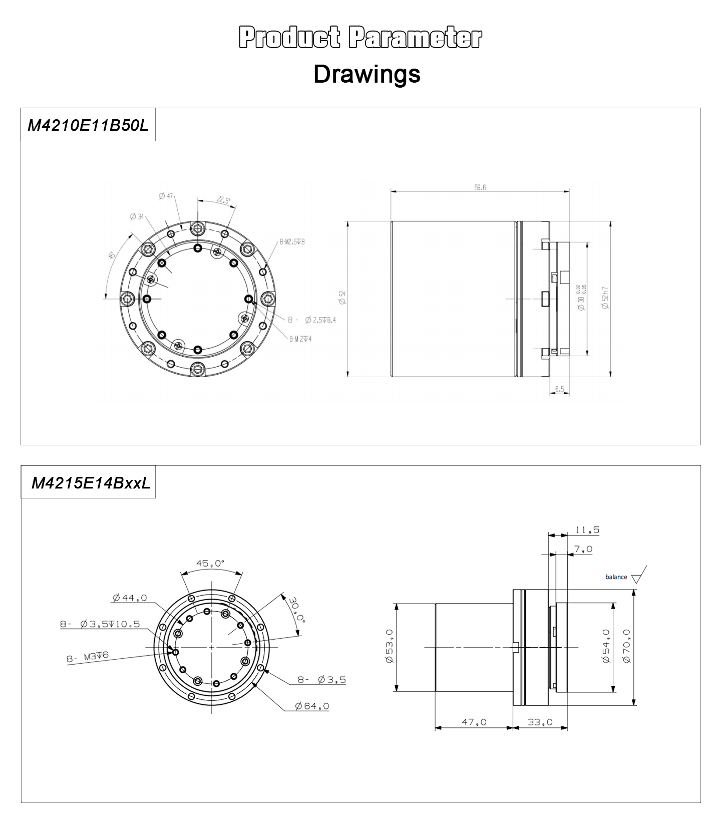
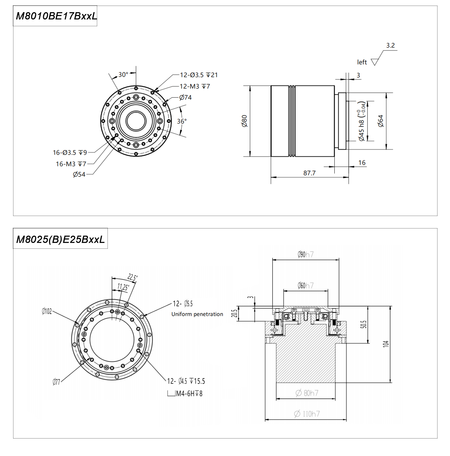
| OD | 110mm | 80mm | 70mm | 52mm |
Product Features
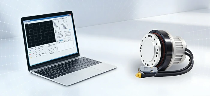
CANopen and Modbus PC software to monitor motor status and modify parameters.
-Isolate CANopen communication according to CiA301 V4.2.0 specificationSupport SDO, TPDO, RPDO.
-Support speed mode, position mode (contour mode, interpolation mode)
-Support heartbeat production and consumption
Built-in low power consumption multi-turn absolute encoder
-15 bit absolute encoder, one lap pulse up to 32768.
-Harmonic reducer, motor, driver and 15bit +16bit encoder are integrated.
-when the robotic joint motor is powered, there is a charging circuit inside to power the -battery.
–When the robot servo motor is powered off, the battery current consumed is only 0.07mA.
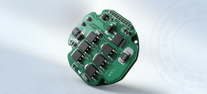
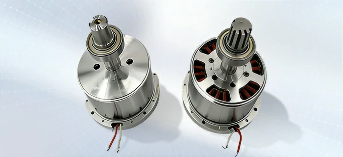
Multi-stage DD motor structure, large torque output
-Multi-Stage Direct Drive Architecture for Enhanced Torque Density
-High Torque Output with Smooth and Precise Motion Control
-Integrated Design for Efficiency and System Reliability
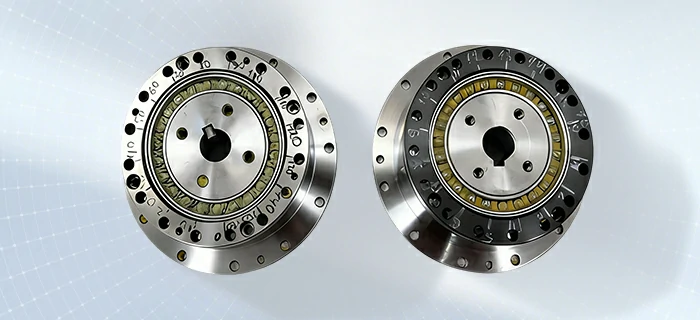
High-Precision Harmonic Drive System
-High-Precision Harmonic Reducer
-Low Noise & Low Vibration Performance
-High-Speed Positioning Capability
-High Reliability for Continuous Operation
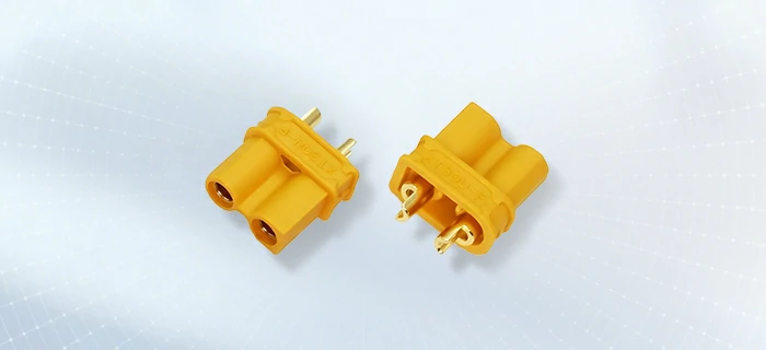
Reasonable interface-power connector
| Terminal Serial No |
Name | Function |
| 1 | +V | Positive DC Power +24V~36V. Negative and positive connections can either directly short the power supply or damage the driver |
| 2 | GND | DC power source. Negative and positive connections can either directly short the power supply or damage the driver |
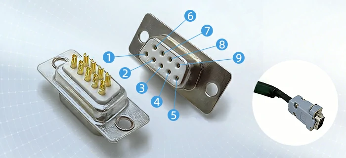
| Db9 Male head | ||||||||
| 1 | 2 | 3 | 4 | 5 | 6 | 7 | 8 | 9 |
| PU+ | PU- | DIR+ | DIR- | WR+ | OZ | COM | CANL | CANH |
| BLUE | BLUE BLACK |
GREEN | GREEN BLACK |
RED WHITE |
YELLOW | BLACK WHITE |
BROWN | WHITE |
| Terminal serial number |
Name | Function |
| 1 | PU+ | Pulse control signal: the rising edge of the pulse is valid; PU- is 3.3~5V at high level, and 0-0.5V at low level. For reliable response to pulsed signals, the pulse width should be greater than 1.2μs. If +12V or +24V is used, a series resistor is required. |
| 2 | PU- | |
| 3 | DIR+ | Direction signal: high/low level signal, in order to ensure the reliable commutation of the motor, the direction signal should be established at least 5μs before the pulse signal.DIR-3.3~5V at high level, 0-0.5Vat low level. |
| 4 | DIR- | |
| 5 | WR+ | Alarm signal output, the internal output is optocoupler NPN.Normally,it is in high impedance state, and it is connected to COM during alarm. |
| 6 | OZ | Encoder zero output. There is a zero signal optocoupler NPN output conduction signal. |
| 7 | COM | The output signal is common to the 485 power supply. |
| 8 | CANL | Can Communication port CANL, built-in isolated power supply |
| 9 | CANH | Can Communication port CANH,built-in isolated power supply |
Product Drawings
Product Application
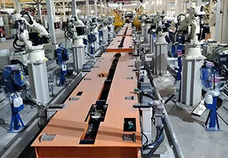 Fully automated production
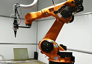 Welding robotic arm
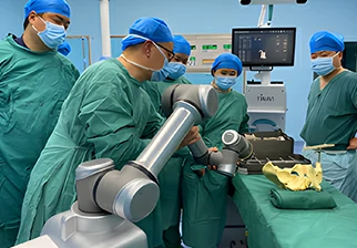 Surgical robot